Frame of this homemade pico class wind turbine is using angle steel because it is cheap, robust, and easily fabricated. Angle steel size is 20x20 mm. Below photo shows wind turbine or windmill is mounted on a steel frame at the top of a steel pipe size 1 1/4 inches. Technically this angle steel frame is not too complicated. Wind turbine design should also consider its beauty or aesthetic. Because it will be placed in an open area and can be seen from a very far distance. A good wind turbine design will add beauty to landscape.


The distance between dynamo fork with turbine blades is 70 mm. The actual distance can still be reduced to about 50 mm. But if the dynamo too forward, then it has higher risk of turbine blades hit. If the distance of 70 mm proved too much, then the dynamo can still be brought to the front with a wooden prop. Wooden prop at the back of dynamo also prevent dynamo dented by fork pressure, which can damage the components inside the dynamo.
There are 4 pieces of 6 mm diameter hole on frame tail. These holes are matched to tail plate holes.
The following photo shows the frame, pole, reducer fitting, and cables.

Cables from the dynamo (at the right, not visible), go to the top of frame, into fitting, and towards bottom of the frame into an hollow formed by an added piece of angle steel. Cables will continue to go down inside steel pipe, exit at the lower end of the pipe and to be connected to regulator and battery.
Turbine frame can rotate 360 degrees to follow the direction of the wind, but the wires are not affected by rotation. Because the frame can rotate to the left and to the right as it follow wind direction, then cables will not be twisted in one direction. Therefore no expensive swivel joint is needed.
Reducer fitting size 1-1 1/4 inches is used to lock turbine frame on to pipe. It is an easy way to install frame on top of pipe, and the fitting will lock quite strong. In the photo below, note the reducer fitting shape that tapers to the top. Note a 10 mm bolt with 35 mm long locks the fitting, so turbine frame can not be pulled up by the wind, when the frame and fitting are installed on the pipe. Look where cables are protected by the bolt. The reducer fitting has thread that fits to pipe thread. It can be seen also that angle steel side is facing down as foundation or sitting and allow frame to turn easily on fitting, not the edge of the angle steel that sits on the fitting.

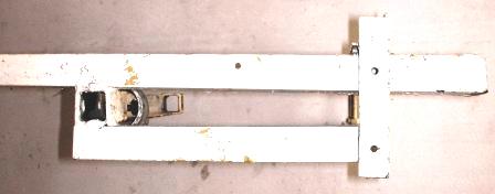
Below photo is showing top view of framer. On the right there are 4 bicycle wheel nuts are welded. Note that the front of frame is reinforced so as to form a square shape. On the left end will be installed a vertical wing or triangular tail fin (unseen).
The following photo is a front view of the frame. Note a nut to hold as turbine bolt at the top, there are 4 pieces of nut are welded in line. Before welding , nuts are attached to the axle bolt but not tightened. And the axle bolt is still not mounted on the turbine in order to facilitate welding. As soon as those 4 nuts are welded to the frame, turn the axle bolt to prevent sticking to nuts until those nuts are cool. Then enclosed those welded nuts with angle steel to form a square hollow steel. At the bottom is a 55 mm width fork, fork width depends to dynamo size. In the center there is frame pole with reducer fittings held in place by bolt. There are 2 long bolts of 10 mm used to adjust distance between fork legs (spacer).

Before turbine is mounted on the frame, replace axle bolt with a longer one. Bicycle rear axle bolt is longer then the front axle one.

Turbine in the photo above is facing down. A longer axle bolt is protruding upward, thread length from locknut is 50 mm. The bolt will be installed to 4 pieces of bicycle wheel nuts which are welded to the frame. After replacing the axle bolt with a longer one, do not forget to adjust ball bearings clearance. Make sure the axle bolt is not too loose but as still can be turned by fingers.

No comments:
Post a Comment
Your positive comment will be highly appreciated to improve this site